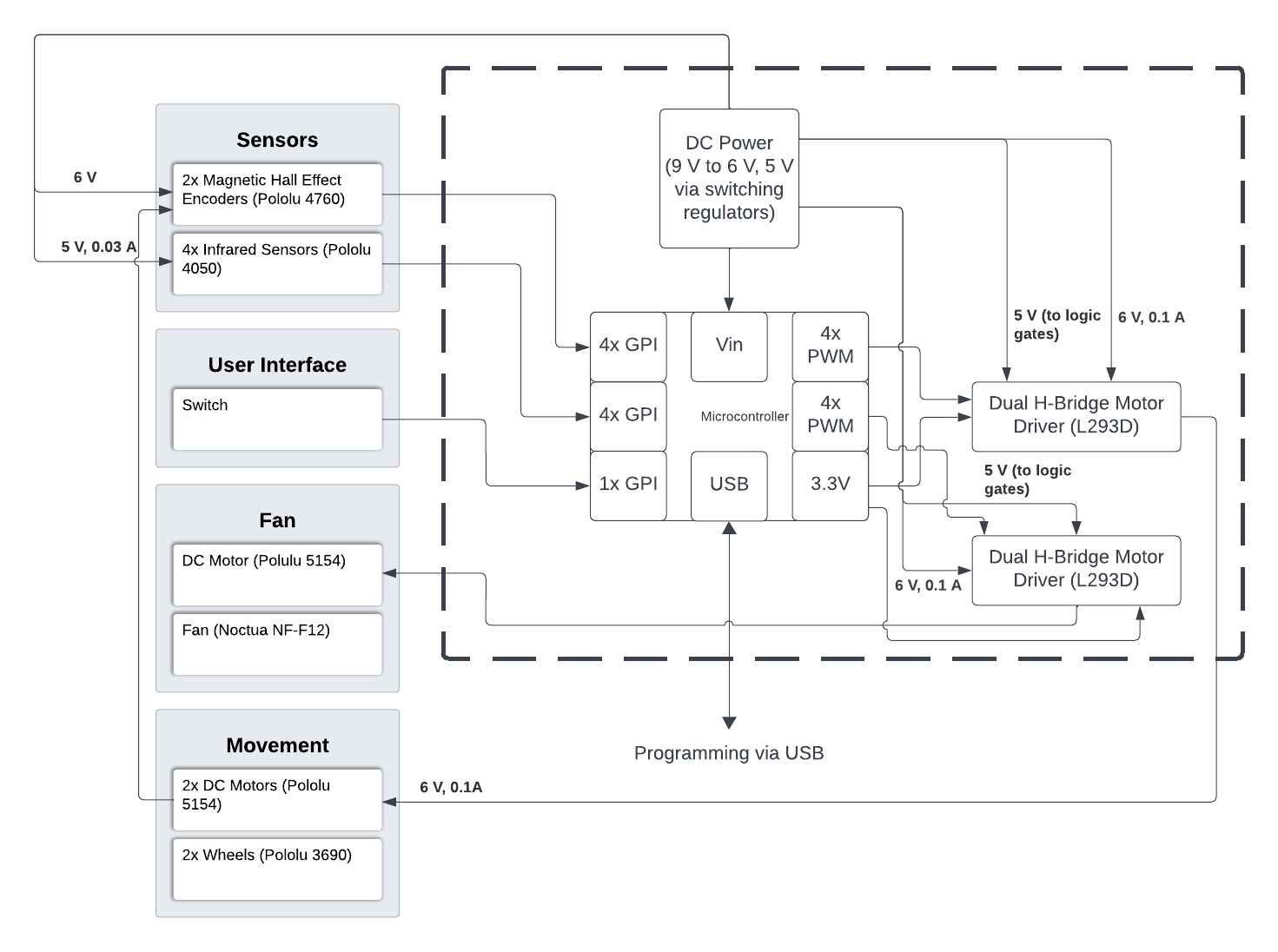
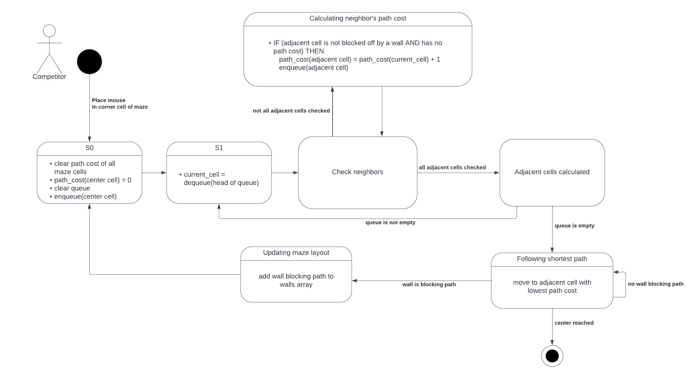
Micromouse Project

Micromouse


Block Diagrams

Hardware

A hardware block diagram. A list of mechanisms is listed on the left side. The Sensors mechanism consists of two parts, labelled '2x Magnetic Hall Effect Encoders (Pololu 4760)' and '4x Infrared Sensors (Pololu 4050)'. The User Interface mechanism consists of one part, labelled 'Switch'. The Fan mechanism consists of two parts, labelled 'DC Motor (Polulu 5154)' and 'Fan (Noctua NF-F12)'. The Movement mechanism consists of two parts, labelled '2x DC Motors (Pololu 5154)' and '2x Wheels (Pololu 3690)'. The DC Motors block in the movement mechanism is connected to the Magnetic Hall Effect Encoders in the sensor mechanism. The electronics are encased in a box with dashed borders. The block labelled 'Microcontroller' has eight sublabels, two reading '4x GPI', two reading '4x PWM', one reading '1x GPI', one reading 'USB', one reading 'Vin', and one reading '3.3V'. The label reading 'USB' is connecting to the words 'Programming via USB', outside of the electronics box. There are two blocks labelled 'Dual H-Bridge Motor Driver (L293D)', each of them connected to the 3.3V sublabel and one 4x PWM sublabel in the microcontroller respectively. However, one Dual H-Bridge Motor Driver block is connected to the DC motor inside the fan mechanism, and the other is connected to the DC motors inside the movement mechanism. Both components of the Sensors mechanism are connected to one 4x GPI sublabel each. The switch is connected to the 1x GPI sublabel. The block labelled 'DC Power
(9 V to 6 V, 5 V via switching regulators)' is connected to the Vin port of the microcontroller block. It is also connected to the Magnetic Hall Effect Encoders with an arrow labelled '6V', the 4x Infrared Sensors with an arrow labelled '5 V, 0.03 A', both Dual H-Bridge Motor Driver with an arrow labelled '5 V (to logic 
gates)' and an arrow labelled '6 V, 0.01 A'.

Software

A software flow chart lock diagram that begins with a stick figure labeled 'Competitor', next to a black circle. The black circle is connected to the S0 block with the text 'Place mouse in corner cell of maze'. The S0 block is then labelled with the bullet points: 'clear path cost of all maze cells', 'path_cost(center cell) = 0', 'clear queue', and 'enqueue(center cell)'. The S0 block is connected to the S1 block, which reads 'current_cell = dequeue(head of queue)'. The S1 block leads to the Check Neighbors block. The Check Neighbors block is connected to the Calculating neighbor's path cost block by an arrow reading 'not all adjacent cells checked'. The Calculating neighbor's path cost block is labelled with 'IF adjacent cell is not blocked off by a wall AND has no path cost THEN path_cost(adjacent cell) = path_cost(current cell)+1, enqueue(adjacent cell)'. The Calculating neighbor's path cost block is connected back to the Check Neighbors block. The Check Neighbors block is also connected to the Adjacent Cells Calculated cost block by an arrow reading 'all adjacent cells checked'. The Adjacent cells calculated block is connected to the S1 block with an arrow labelled 'queue is not empty', and the Following shortest path block with an arrow labelled 'queue is empty'. The following shortest path block is labelled 'move to adjacent cell with lowest path cost'. It is connected to itself with an arrow labelled 'no wall blocking path', the Updating maze layout block with an arrow labelled 'wall is blocking path', and a black circle with a ring around it with an arrow labelled 'center reached'. The Updating maze layout block is labelled with 'add wall blocking path to walls array', and is connected to S0.

Parts

Prices in USD, without taxes.

Item Brand/Type Quantity Cost per unit
Microcontroller Nano 1 25
Rechargeable Batteries 9V Li-ION 1 24
On/Off Switch TCNJ 1 0
Chassis Self-Determined 1 0

Website


This is where the design of the website will be detailed. Stay tuned for more updates.

Website Component Resource Used
Layout Self-Determined
Color Palette Catppuccin
Heading Font Gudea
Body Font Verdana

Validation


Valid CSS!